I finally decided to correct the opening for the compass. My idea was to plug the hole with plastic rod, cut it flush and then drill the new hole, in the right place this time. I wanted to avoid any type of filler, because I knew this would just flake away when I started drilling. But I was pretty sure that a plug of plastic, cemented into place, would be as strong as the original card.
I tried it on a piece of scrap plastic card first, and it worked perfectly. So I went ahead with the instrument panel, and it worked perfectly again. Phew.
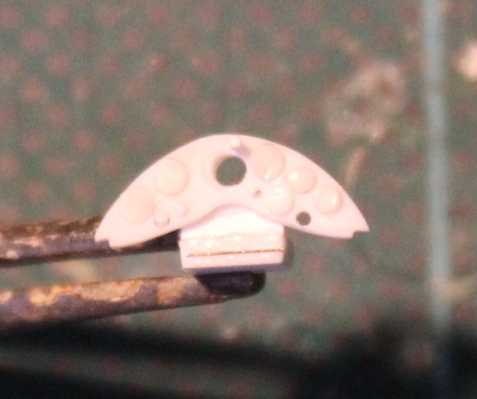
This is the result:

I also decided to add a bit more detail before painting, particularly the boost gauge and the metal box that I assumed was the map case.
To start with, I had assumed that the boost gauge was mounted on one of the uprights of the fuselage framework. But my internet searches turned up pictures of an aftermarket instrument panel that had the gauge hanging off the instrument panel as though on a bracket. In the absence of other information, I decided to follow this example But then, after starting work, it occurred to me to return to my main printed reference (David Luff, 1987), and actually read some of the relevant sections. Previously, I had skimmed over these and relied mainly on the diagrams and photos (which are invaluable). Anyway, in Chapter 3, he provides the answer. The boost gauge was mounted on the port side strut of frame no. 2. So I tore off the improvised bracket I had made. The gauge will have to be added to the framework after painting. Fiddly, but not too difficult. At least I have an answer.
I still had to decide about the map case, and here my closer reading of David Luff paid off again. It was a combined map case and diagram box, as it turns out, so I was pretty close.
It was pretty straightforward to model: a piece of plastic strip sawn to length, with a length of 0.3mm nickel steel to show the hinges on the front. (I think they're hinges.) I had to make a guess at the depth, but my map case came out at about 3x4mm or pretty close to A4. I imagine there's information available about the size of maps used by RAF pilots in the 20s and 30s, but this is a reasonable guess I think.
I still wasn't clear how the box was mounted, but I decided to use a simple bracket made out of plastic strip. Later on, the instrument below the panel will be added to this. And on this subject, Luff came good again. It was a Schilovsky-Cooke turn-and-bank indicator.
So here is how the instrument panel looks now:
Incidentally, what you tend to see in kits and aftermarket products is pretty much just the front of the map and diagram case. In reality, I expect that it would have extended back a bit further to accommodate the maps, and that's what I've shown. But that just illustrates the hazards of relying too much on existing products instead of historical sources.
Anyway, that's all for now. More quite soon.
No comments:
Post a Comment