Sunday, 9 March 2025

Bulldog - paint!

 I've finally got round to doing some painting. This was something of a psychological hurdle, for three main reasons:

  1. It was going to involve a lot of airbrushing, which is not my strong point
  2. It would involve using brands of paint that I haven't used before
  3. Nameless fears

At last, I made a start by getting the compressor out to see if it still worked. And this is where the nameless fears started to take a more definite shape. It was more than twelve years since I had last used the compressor, and in that time, as I immediately found out, the air hose had perished. My immediate thought was to get a new compressor; but I 've already spent quite a lot of money on this project, and so I decided it would be better to try to and replace the hose, though obviously it wouldn't be quite as enjoyable. So I went to my local car parts shop and got some fuel hose, and as it turned out this did the job quite well. Those circlips really make the new hose look as though it's meant to be there.


 I was going to start with the interior framework and associated parts (the fuselage might still need a bit more work before painting, but more on that later). According to David Luff, all steel fittings were protected from corrosion by a paint-dipping and stove enamelling process. And there were also a few brass bits to be painted at this stage.

These are the paints I decided on. I would give all parts a coat or two of SMS Black, and then give the brass parts a further coat of AK Extreme Metal Brass.

This is the bits after painting:

And this is what they look like after they have dried for a while:


 Not a bad result, but I'm not completely sure about the finish I've got. You would expect it to be fairly glossy, but I'm not sure this is exactly right. I might do a coat of half-gloss clear lacquer to see if that improves things, but I won't rush into it.

Anyway, this amounts to real progress, and the nameless fears did not amount to much in the end. More soon!

Wednesday, 5 March 2025

Bulldog - bits and pieces

 I have managed to get the seat to fit. I realised that it was sitting too far back on the bearers, so all I had to do was break them off and then reattach them so that the seat is further forward. And now it fits very nicely. So my careful calculations were correct after all. No need to trim the seat or do anything drastic. It just shows that when you face a problem like this, it is best to leave it for a while, and definitely not do anything hasty.


 There was still one remaining problem. The adjustment lever got in the way of the framework and prevented the seat sitting centrally. So I broke that off as well and made a new one and then repositioned it so that it's clear of the framework; and I made a better job of the release button this time.


 While I was mulling over the problems with the seat, I realised that there was a bit more work to do at this stage, before painting and assembly. The fuselage itself is pretty much ready, but then there's the centre section. In the kit, the whole lower mainplane is one piece, and attaches to the fuselage via a big rectangular location lug, which engages with cutouts in the fuselage halves. In theory, the big rectangular location lug will be visible after the fuselage is closed up, and there lies the problem.

For the sake of completeness, I decided to tidy up this area and make it a bit more representative of the real thing. Another close reading of David Luff was called for, and this threw up enough info to come up with a basic concept:

Apparently, the struts connecting the fuselage to the centre section formed an M shape, making a total of 4 connections to each of the two spars. There was a central bay, with an aerofoil section either side, formed with 3 ribs. The lower surface of the central bay was covered with an aluminium panel, and the aerofoil sections were covered with canvas top and bottom. In the absence of other information, I assumed that the upper surface of the central bay was not covered: this would save weight if nothing else.

 What this amounted to in this build was the following work schedule:

  1. Remove location lug and carve out a recess that represents the central bay
  2. Enlarge opening in fuselage halves to correspond to central bay
  3. Add centre section struts
  4. After painting, add tiny pieces of rod to represent the fore and aft spars.

 Here is what I ended up with for the centre section struts (you might notice that I've already added these struts in the pics above):


 And this is what it looks like in a test fit:


 All very promising. And I will definitely make a start on the painting quite soon.

Sunday, 23 February 2025

Bulldog - control column

Just finished the control column. It's a mixture of brass tube and nickel steel rod, because that's what I had to hand. The spade grip was made by wrapping 0.33mm nickel steel rod around the shank of a drill bit to end up with a tiny helix, then cutting through a few of the turns at once and choosing the best of the resulting pieces. I seem to remember that's how they used to make the links for chain mail.

This is the result. I've got the control column pushed forward slightly relative to the aileron rockshaft, so that I can make the elevators droop a bit when I eventually get round to them:

And that's all the progress I've made this weekend. Not very impressive on the face of it, but it does represent something of a landmark, because the next stage is to do some painting.

But I'm not going to rush into that. First, I've got to decide what paint to use and then I've got to get the hang of using it with an airbrush. So I'm going to have to do a bit of experimentation before making any more progress.

Anyway, more in due course.


Friday, 21 February 2025

Bulldog - more work on seat

 After the last post, I realised that the seat wasn't quite right. According to the available kits and aftermarket products, the seat back should have a noticeable taper towards the top. I know, I know. But I thought I might as well go with the consensus.

The next day, I set to to work making a new one. Now that I'd worked out the basic methods, it didn't take too long. But I was a bit hasty with the cutting out, and I ended up with something that was not quite square: the base of the seat was a kind of rhombus, varying in depth by about 0.1mm from side to the other. Not very much, and hard to measure, but the human eye is very good at detecting this sort of anomaly. And it just looked very wrong.

I decided to have another go, and this time make better use of the tools at my disposal. So I drew up a cutting guide in TurboCAD and taped it to a piece of 0.5mm plastic card. Then I cut out the pieces using a steel rule as a guide. In the picture below, the two pieces are separated by a small gap. If you don't have the gap (as I discovered on my first attempt), then when you cut out the second piece, the knife blade can be diverted from its course by the cuts you have already made for the first piece, and you end up with a shape that is not quite as clean as it could be.

Once I'd got the pieces cut out, I cleaned them up and added plastic strip for the sides. This time I made my life easier by adding the pieces and then cutting them to size once the glue had dried. And I remembered to take pictures:

While I was at it, I decided to have another go a the adjustable seat mechanism, using the Airfix 1:48 model as a guide, because I never learn. I ended up with these bits:
But this is where it all started to go wrong. I had a bearer and a sort of tubular framework for each side, but once it came to gluing them together, I took my eye off the ball. In order for the seat to sit properly on the framework, the bearers have to be exactly aligned, but somehow I got one of them almost 1mm out vertically from the other. Also, the struts were much too big and so the seat ended up much too high. I know the seat was adjustable, but even so...
 
I had a couple of hasty attempts at putting things right, but in the end I decided I would have to have another go at the mechanism, and so I called it a day.
 
Next day, I redrafted the mechanism and set to work rebuilding it. For the previous version, I had used 0.4mm Plastruct rod, but I had run out of this, so I used 0.5mm Evergreen instead. I had the feeling this would be a bit over scale; but on the other hand, it was bound to be stronger. As before, I printed out an assembly jig and taped the plastic rod to it as I went along. But this time, I added the bearers before cutting to size.

 
After this, I cut along the baseline of the seat using a guillotine (I forgot to take a picture), and this is what I ended up with:

Then all I had to do was glue the bits together and add the adjustment lever. The lever was made from 0.4mm Albion Alloys brass tube, with 0.1mm nickel rod inserted for the release button. Unfortunately, because I cut it to something like scale length, I don't think you're going to be able to see the button.


The next thing was to do a trial fit.

And unfortunately it didn't fit.

The problem, as I discovered, is that the adjustment gear fouls the diagonal cross-bracing at the rear of bay no. 2, and this is probably one result of the compromise that had to be made between scale dimensions and the thickness of the fuselage mouldings. I think a further compromise will be necessary. In all probability, either the cross-bracing or a part of the seat mechanism will have to go. But rest assured, I'm not going to do anything hasty, especially since I've already poured myself a well-earned glass of cab sauv.

But one outcome or other soon!


Update: in the end, I removed the cross-bracing. It came away quite easily with just a bit of tweaking so that's a relief. The seat still doesn't fit exactly - the top edge comes up against the bulkhead and so prevents the whole seat from tilting back far enough. As a result, the bearers don't quite meet the cross-strut at the back. But the gap is less than 1mm, so nearly there! If necessary, I could shave a bit off the top of the seat back. Or I could decide that I don't actually mind the gap. More on this later probably. There's no great hurry.

Monday, 17 February 2025

Bulldog - Seat

 I've made a start on the seat. Once this is done, it's time for a batch of painting. Then I can start putting everything together. I still have to decide what paints to use, but more on that later.

 The first thing I tackled was the headrest, or rather the bulkhead that the headrest is mounted on. I just carved this from plastic card with my usual trial-and-error technique. As usual, this seemed rather a hopeless task to start with, but in the end it went quite well and I got quite a good fit. I decided to carve the headrest itself separately and add it after painting, so the only other detail to attend to at this stage was the slot for the Sutton harness. This turned out to be pretty simple to do. I just drilled a central pilot hole, then used the same drill bit as a sort of file or router to open it up into a slot, with the result you see here:

This is one item that can be sensibly be treated as an integral part of the fuselage framework, so I've cemented it into place, and this is what it looks like:


 The next job is the seat itself, and this is where it gets slightly difficult. My main printed reference (David Luff, 1987), says that the seat was adjustable, and provides some useful details of the mechanism, but I can't find any photos or diagrams of the seat or the adjustment gear. So in the end, I have had to fall back on existing products. I seem to remember that I warned against this in my previous post, and I am aware of the danger that I will end up effectively making a model of other models; but this is a risk I will have to take in this case.

What I ended up doing was studying the online instructions for the Airfix 1:48 Bulldog and then trying to build something that represented what the Airfix kit is trying to represent. It would have been nice to effectively reverse-engineer the Airfix moulding to understand the workings of the mechanism. But in the end, I just decomposed it (as we say in software engineering), to end up with a set of individual parts that look like this:


 I think it should look reasonably convincing once it's in place. But that's enough for one day. More soon.

Bulldog - more work on instrument panel

 I finally decided to correct the opening for the compass. My idea was to plug the hole with plastic rod, cut it flush and then drill the new hole, in the right place this time. I wanted to avoid any type of filler, because I knew this would just flake away when I started drilling. But I was pretty sure that a plug of plastic, cemented into place, would be as strong as the original card.

I tried it on a piece of scrap plastic card first, and it worked perfectly. So I went ahead with the instrument panel, and it worked perfectly again. Phew.

This is the result:


 I also decided to add a bit more detail before painting, particularly the boost gauge and the metal box that I assumed was the map case.

To start with, I had assumed that the boost gauge was mounted on one of the uprights of the fuselage framework. But my internet searches turned up pictures of an aftermarket instrument panel that had the gauge hanging off the instrument panel as though on a bracket. In the absence of other information, I decided to follow this example But then, after starting work, it occurred to me to return to my main printed reference (David Luff, 1987), and actually read some of the relevant sections. Previously, I had skimmed over these and relied mainly on the diagrams and photos (which are invaluable). Anyway, in Chapter 3, he provides the answer. The boost gauge was mounted on the port side strut of frame no. 2. So I tore off the improvised bracket I had made. The gauge will have to be added to the framework after painting. Fiddly, but not too difficult. At least I have an answer.

 I still had to decide about the map case, and here my closer reading of David Luff paid off again. It was a combined map case and diagram box, as it turns out, so I was pretty close.

It was pretty straightforward to model: a piece of plastic strip sawn to length, with a length of 0.3mm nickel steel to show the hinges on the front. (I think they're hinges.) I had to make a guess at the depth, but my map case came out at about 3x4mm or pretty close to A4. I imagine there's information available about the size of maps used by RAF pilots in the 20s and 30s, but this is a reasonable guess I think.

I still wasn't clear how the box was mounted, but I decided to use a simple bracket made out of plastic strip. Later on, the instrument below the panel will be added to this. And on this subject, Luff came good again. It was a Schilovsky-Cooke turn-and-bank indicator.

So here is how the instrument panel looks now:


 Incidentally, what you tend to see in kits and aftermarket products is pretty much just the front of the map and diagram case. In reality, I expect that it would have extended back a bit further to accommodate the maps, and that's what I've shown. But that just illustrates the hazards of relying too much on existing products instead of historical sources.

Anyway, that's all for now. More quite soon.

Tuesday, 11 February 2025

Bulldog - instrument panel

 This is a job of two halves: one much more fiddly than the other, and the other much more fun. First of all you have to cut out the instrument panel itself and make it fit inside the fuselage mouldings, then you have to add the instruments and various controls.

You can probably work out which stage of the job is which.

When it comes to making the basic panel shape, one obvious solution comes to mind: you get an impression of the fuselage with Plasticine, and then just draw round it on a piece of plastic card and cut out. But Plasticine is rather a blunt instrument for forming a tiny part like this, and it would be difficult to get an accurate outline. I think there are purpose-made moulding compounds available now for doing this kind of thing, but I decided just to do it by trial and error, using the following rather ad-hoc technique:

  1. Cut out a rectangle of plastic card the right height, that exactly matches the width of the framework.
  2. Cut little rebates so that it drops into place (this matches the design of the original)
  3. Roughly shape the panel
  4. Repeatedly, slot it into position into the framework and offer up to one fuselage half or the other, until it fits exactly

And this, as you will have worked out, is the fiddly bit. One of the problems is that it's difficult to hold the panel in place as you do the fitting. Another is that it's easy for the panel to push the framework out of position when you're doing the fitting, so you think you've got a good fit but in reality the panel is still too large. You've got to be on the alert for this.

Here you see the fitting in progress. You might notice that somewhere along the way I've added the engine bay bulkhead, with a location tab so that the framework just drops into place. This makes the whole test fit procedure much easier and less error-prone.


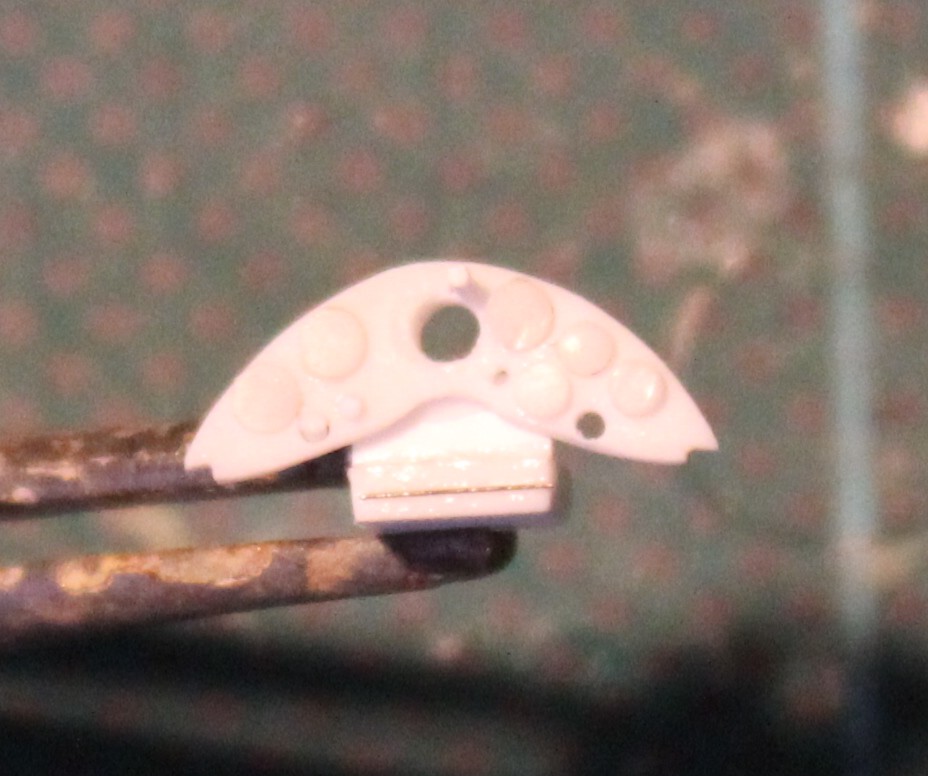
 And in the end, I got a reasonably good result. This is the basic panel I arrived at:

At this stage, I can be fairly sure that the starboard side is a pretty good fit, and the whole thing is the correct width because it fits into the framework. When it comes to final assembly, I will glue it into place in the framework and then glue the framework into place on the starboard side. Then, when everything is set, I can do a bit more shaping if necessary to make it fit the port side.

So, onto the fun bit.

I have decided to use a two-pronged approach for attaching the instruments and controls.

  1. For the larger ones (above 1mm), cut discs of plastic rod and sand them between two pieces of wet and dry. Then cement them into place.
  2. For the smaller ones, drill a location hole, push through a length of plastic rod and then cement on the reverse side. When all is set, trim off the excess. To neaten up the ragged cut end, either sand down or just douse in liquid poly. I can decide later about that.

 Also, the build will be a two-stage process. The panel and most of the instruments had a black finish, so I can do all these in one go before painting. Some other things like the brass switches I'll add after painting.

Here is the panel almost ready for painting:

There are still a few additional bits to make:

  1. A compass, to be mounted behind the circular cut-out
  2. An instrument to be mounted below the panel (an inclinometer?)
  3. A boost gauge, to be mounted on the framework

 You may notice that the cut-out for the compass is slightly off-centre. I will have to decide whether to do anything about this. I certainly don't want to start again.

Anyway, one way or another, more soon.